- Your Government
-
Our Community
-
- About St. Helens History of St. HelensState of the CityCourthouse Dock Camera
- Local Events City Calendar Citizens Day in the ParkRecreation Activities Discover Columbia County Sand Island CampingKeep It Local CC
- Community Resources City Newsletter City Social Media Emergency Services New Resident InformationProtecting Our Environment
-
-
Business & Development
-
- Local Business Directory Get a Business License City Bids & RFPs Broadband Study
- Business in St. Helens St. Helens Advantages Directions & Transportation Incentives & Financing Resources for Businesses Business Guide Columbia Economic Team Chamber of Commerce
- Current City Projects Waterfront Redevelopment Public Safety Facility Strategic Work Plan
-
-
How Do I?
-
- Apply for a Job Apply for a Committee Find A Park Find COVID Info Find Forms Follow St. Helens - Facebook Follow St. Helens - Twitter Follow St. Helens - YouTube
- Get a Police Report Get a Business License Get a Library Card Get a Building Permit Newsletter Signup Past Public Meetings Pay My Water Bill
- Public Records Request Report a Nuisance Register for Rec Activity Reserve a Park Sign Up for the 911 Alerts Universal Fee Schedule
-
What is a Ranney collector well?

The City of St. Helens Ranney collector well system
The source of the City of St. Helens drinking water is supplied from Ranney collector wells. The Ranney well is a deep well that was mechanically dug down, 80 feet, into the West river bank of the Columbia River. The bottom of the well rests in a zone of water saturated rock, sand and gravel that lays far below the riverbed of the Columbia River. This zone is called an aquifer. (aqua-fur)
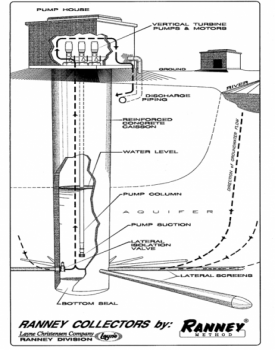 The Ranney collector well casing is a very large, vertical, steel reinforced, concrete cylinder called a caisson (case-on) that has an outside diameter of 16 feet. The caissons' in St. Helens, have 7, stacked, steel reinforced sections, called “lifts”. Each “lift” is 12 feet high, with a 13 foot inside diameter, (the walls of the caisson are 18” thick). Each “lift” or section of the caisson, has a tongue and groove joint on the top and bottom of the cylinder that allows each lift to be stacked, aligned, joined and sealed and tightly locked together.
Note from Howard (Howie) Burton: The pictures and photos in this article, and slideshow, are not actual pictures of the St. Helens Ranney collector well installation but are for the sole purpose of reference and educational use only. The pictures are a collection of photos of several Caisson well construction projects from across the U.S.A., and Internationally, that I found about the subject to help you, the viewer, visualize what a Ranney collector well is, how these wells are constructed and brought into service. I cannot authorize or grant permission for the use of these pictures or photos, because they are not mine to give. I want to take this moment to express my appreciation for all the contributors whose illustrations and photos made this article more enjoyable and more colorful. Thank you so much.
Construction of the Ranney collector well Caisson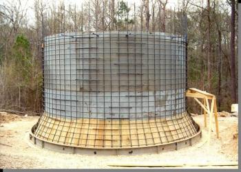
The first section of the caisson is a beveled cutting foot (left). The next section fitted and stacked on top of the "foot" (right) is the ported section that the laterals will be driven out through into the aquifer.
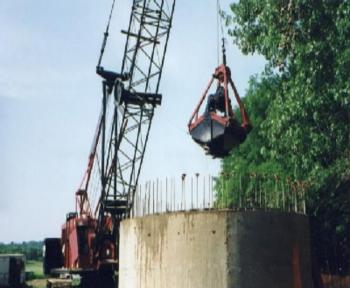
Each of the sections or "lifts", are built on site. The inner concrete wall of this cutting foot has been built, and here you see the rebar that has been fabricated around the inner caisson wall. The outer concrete form will be built around the rebar and filled with concrete completing this first section of the caisson. The "cutting foot" is carefully positioned on the river bank where the well will be dug. An overhead crane with a clam shell attachment is 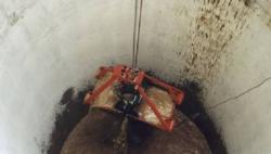 used to scoop out the mud, sand, rocks and gravel from the inside of the caisson. (as pictured here) As the mud, gravel and water is removed from the inside of the caisson, the “lift” or next section of the caisson, steadily lowers down into the river bank. When a lift has lowered about 10 feet into the riverbank, another lift is stacked on top, locked and sealed into place and the digging resumes until the desired depth of the well is reached. (St. Helens caisson floor is 80 feet deep)
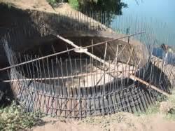
When the caisson reaches the designed well depth, a grid-work of steel reinforcing rods, rebar, is constructed creating a floor inside the caisson, as seen in the picture at the lower left. (The beveled part of the 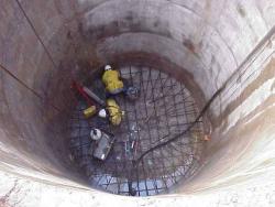 cutting foot of the caisson is 12' below the workman's feet.) They are standing on the water saturated gravel of the aquifer, which is about 40' below the Columbia River riverbed. A pump is running constantly as the workman are building the floor because the surface of the Columbia river is 50' to 70' above their heads on the outside of the caisson. By the nature of gravity and natural hydraulics, the water is trying to flood into the caisson by coming up through the gravel floor. The floor they are building is being attached to the ported section of the caisson. When the reinforcing grid work of steel is installed, concrete is then poured over the rebar to a depth of 42”. The concrete creates a permanent plug that seals the inside of the caisson from the surrounding aquifer, and makes a solid concrete floor at the bottom of the collector well. The only way water will come into the caisson is through the infiltration gallery of screened pipes that will be driven out into the surrounding aquifer.
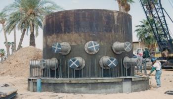
The Infiltration Gallery (laterals)
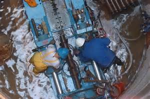
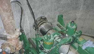
The second section of the caisson that was stacked on top of the beveled cutting foot, is where the infiltration gallery lateral ports are located. Through these ports, the lateral screens are going to be pushed, or "jacked" out into the aquifer using the green and blue hydraulic tools seen in the pictures below. The hydraulic jacking tool is bolted to the concrete floor and the walls of the caisson, then a 10' foot section of 10 inch, slotted ductile iron steel pipe, called laterals, are pushed out through the port from the caisson, and penetrate the sand and gravel aquifer. (As you can see in the cutaway illustration at the top of the page, the infiltration laterals are arranged out from the caisson like the spokes of a wheel). The first section of the screened, or slotted, lateral has a beveled, or pointed, end plug to close off the open end of the intake pipe as well as assisting the screen to be pushed out into the gravel aquifer. The screened infiltration gallery laterals are 40 feet below the riverbed of the Columbia River and 60 to 70 feet below the static surface of the Columbia River.
A side point of interest: The layers of mud, silt, sand and gravel of the Columbia riverbank that the water flows through into the infiltration gallery laterals, provides an abundant, consistent, dependable, supply of high-quality source water, with a constant year round, non-fluctuating temperature, low turbidity (not muddy or murky looking) as well as low levels of undesirable constituents and contaminants, such as viruses, bacteria, pesticides, petroleum and pharmaceuticals. The riverbank filtration action also provides an additional barrier to reduce precursors (organics like algae, peat, tannin, leaves, submerged decaying trees, petroleum from boats etc.,) that can form disinfection byproducts during treatment.
Intake screens on the infiltration gallery
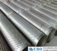
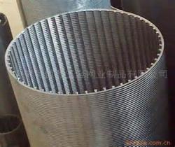
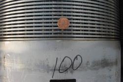
There are several infiltration gallery radial well intake screen configurations, some are machine slotted perforations, (left) and another is a continuous wedge wire wrapped around a framework of stainless steel ribs, (center). Generally the spacing between the wire wrapped screens is 1/8" and the machine slotted perforations are 1/4" to 3/8" wide. (The spacing between the wire wound screens is given perspective when compared to the size of a penny. (right) You can also see behind the penny, the framework of ribs the wire is attached to).
NOTE: There are more pictures of various screens in the slideshow
A short Ranney collector well history
The well is named after its inventor, a petroleum engineer, Leo Ranney. In the early 1920's, he built his first oil collector well in a Texas oilfield. His idea was that he could gather larger quantities of oil by digging a single, large borehole (caisson) and then horizontally punching out from the caisson, with hydraulic jacks, slotted collector pipes into the oil rich bearing strata. The dozens of screened collection pipes would let the oil drain from the surrounding area and flow, by gravity, into the caisson. His concept was that he was going to be able to gather more oil from a larger underground oil field with his central caisson, than drilling many individual wells. When the bottom fell out of oil prices in the early 1930's, Mr. Ranney's method of an oil collector well technology was applied to tap into another vital and extremely valuable natural resource, a fresh, rich, clean, underground water supply to meet the demand for a pure drinking water source. The first Ranney collector wells to recover groundwater was dug in London, England in 1933. In 1936 the first Ranney collector well in America was installed in Canton, Ohio. Since then, hundreds of these wells have been used all over the world, including St. Helens, Oregon. Return to top
Return to the Water Filtration Facility Home page
Questions or comments.
Send us an e-mail:
or Phone: 503-397-1311
Click any thumbnail image to view a slideshow


")